 +852 60984748
Leave Your Message
Choosing the right Ptc Heating Element in 2026 requires more than comparing wattage and price. Engineers must match thermal output, voltage, surface temperature, airflow, humidity, and installation space. A compact heater can warm a vehicle cabin quickly, yet poor airflow may create hot spots, noise, or premature failure. The practical question is simple: where will the heat go?
Industry demand is becoming more performance-focused. The International Energy Agency reported that global electric car sales exceeded 17 million in 2024, creating stronger demand for efficient cabin and battery thermal systems. The IEA also notes that building cooling and heating loads are becoming more important as temperatures and electrification increase. These trends favor self-regulating PTC technology, especially where stable temperature control and reduced overheating risk matter. However, efficiency claims require careful testing. Results change with ambient temperature, mounting pressure, insulation, fan speed, and control strategy.
A reliable selection process should begin with the application, not the catalogue. Check the required heat-up time using a real enclosure, duct, or battery compartment. Confirm dielectric strength, operating life, moisture resistance, and thermal cycling performance. Independent certification can strengthen confidence, but it does not replace system-level validation. Market forecasts from commercial research firms vary widely because product categories are defined differently. That uncertainty deserves attention. The best Ptc Heating Element is not always the smallest or cheapest option. It is the component that delivers predictable heat, safe operation, and stable performance under actual conditions. Some designs still need refinement. That is normal engineering.
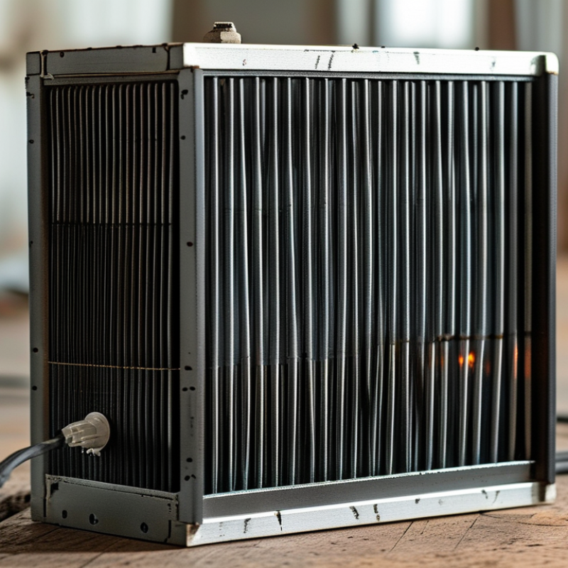
How to Choose the Right PTC Heating Element in 2026?
Understanding how a PTC heating element works makes selection more practical. PTC means positive temperature coefficient. As the ceramic element heats, its electrical resistance increases. Current then decreases naturally, limiting temperature rise. This self-regulating behavior differs from a simple resistance wire, which may continue drawing substantial current without careful control.
The effect depends on the material’s Curie temperature, applied voltage, airflow, and heat transfer path. In a compact air heater, aluminum fins spread warmth while a fan removes heat from the surface. In a seat or enclosure heater, limited airflow changes the thermal balance. Check rated power, operating voltage, starting current, surface temperature, and expected ambient conditions. A component that performs well in a laboratory may respond differently inside a dusty, tightly packed housing.
I usually compare the heating curve, not only the wattage. Measure warm-up time and temperature at several airflow rates. Do not assume “self-regulating” means risk-free. Poor contact, blocked vents, or an incorrect supply can still cause failure. Engineers should also review insulation, moisture resistance, mechanical stress, and long-term resistance drift. A small test fixture often reveals problems that a datasheet hides. This step can feel excessive, but skipping it is harder to justify after installation.
| Selection Dimension | Typical Data or Range | Operating Principle | Recommended Application | Advantages | Important Design Consideration |
|---|---|---|---|---|---|
| PTC Material | Barium-titanate-based semiconductor ceramic | Electrical resistance rises sharply near the material's Curie temperature, reducing current as the element heats. | Self-regulating air heaters, small appliances, battery thermal systems and equipment cabinets. | Inherent temperature-limiting behavior and reduced risk of overheating under normal conditions. | Performance depends on ceramic formulation, geometry, heat transfer and operating voltage. |
| Cold Resistance | Typically from a few ohms to several hundred ohms | Resistance is lowest when the element is cold, allowing a higher starting current. | Applications requiring rapid warm-up after power is applied. | Fast initial heat generation. | Check the power supply's inrush-current capability and wiring capacity. |
| Steady-State Resistance | Usually much higher than cold resistance; the exact value is design-specific | As temperature rises, resistance increases and electrical power naturally decreases. | Continuous heating where stable output is preferred over precise closed-loop control. | Helps limit current without a conventional mechanical thermostat. | Do not calculate operating power from cold resistance alone. |
| Common Supply Voltage | 5 V, 12 V, 24 V, 48 V DC; 110–120 V or 220–240 V AC designs are also available | Electrical power is determined by voltage, resistance and the heat-transfer environment. | Low-voltage portable equipment, industrial controls and mains-powered heating products. | Broad compatibility with different power architectures. | Select a rated voltage that matches the supply and verify insulation and creepage requirements. |
| Typical Rated Power | Approximately 5 W to 1,500 W, depending on size, voltage and airflow | Power output changes as the element temperature and thermal load change. | From compact enclosures and sensors to HVAC-related air-heating modules. | Flexible sizing for low- and medium-power heating tasks. | Use measured thermal performance rather than nominal wattage alone when sizing the heater. |
| Surface or Control Temperature | Common designs are approximately 60–240 °C; the specified value is application-dependent | The selected ceramic composition establishes a resistance transition near its reference temperature. | Air warming, condensation prevention, frost protection and controlled enclosure heating. | Can provide approximate thermal stabilization without complex feedback control. | PTC self-regulation does not guarantee an exact product or air temperature; airflow and mounting are critical. |
| Heating Medium | Air, aluminum heat sink, metal plate or another thermally conductive structure | Heat is transferred by convection, conduction or a combination of both. | Fan heaters, duct heaters, defoggers, warm-air modules and contact heating assemblies. | One ceramic technology can support different thermal layouts. | Never operate a high-power element without the heat-transfer path specified by its design. |
| Airflow Requirement | Natural convection or forced airflow; forced airflow generally increases heat dissipation | Greater airflow removes heat more efficiently, allowing the element to draw more power before stabilizing. | Portable heaters, ventilation systems and electronics-cabinet climate control. | Output can adapt partly to changing airflow and thermal load. | Blocked airflow may raise local temperatures and reduce useful heat delivery. |
| Warm-Up Behavior | Fast response is common, but actual warm-up time ranges from seconds to several minutes | High cold-state current produces rapid initial heating, followed by current reduction as resistance rises. | Defogging, hand dryers, air preheating and short duty-cycle equipment. | Quick startup without a separate temperature sensor in simple systems. | Warm-up time depends on mass, airflow, ambient temperature, voltage and mounting. |
| Temperature Regulation | Self-limiting rather than precision regulation | The positive temperature coefficient reduces current as the element approaches its designed transition region. | Applications with moderate temperature accuracy requirements. | Simple control architecture and reduced dependence on switching components. | Use a thermostat, thermistor, sensor and controller when tight temperature tolerances are required. |
| Energy Efficiency | High efficiency is possible when heat is delivered directly to the target medium | Electrical energy is converted into heat at the element, while self-regulation reduces unnecessary current under changing loads. | Localized heating and systems where heat can be transferred with minimal losses. | Less overshoot and simpler thermal management than many fixed-resistance heaters. | System efficiency still depends on insulation, airflow, heat leakage and control strategy. |
| Mechanical Construction | Typical forms include bare ceramic chips, finned air-heater assemblies and insulated modules | The housing and fins increase surface area and provide electrical or mechanical protection. | Open-air heating, enclosed equipment and applications requiring guarded live parts. | Available in compact, modular and application-specific configurations. | Confirm dimensions, mounting method, vibration resistance and insulation construction. |
| Electrical Isolation | Choose insulated or electrically exposed construction according to the system design | The ceramic may generate heat while the surrounding frame, fins or terminals provide different electrical potentials. | Consumer equipment, industrial panels and metal duct systems. | Insulated designs can simplify integration and improve user safety. | Verify dielectric strength, leakage current, grounding and applicable safety requirements. |
| Operating Environment | Ambient temperature, humidity, dust, vibration and altitude must match the element specification | Environmental conditions influence heat transfer, insulation resistance and component lifetime. | Indoor equipment, vehicles, outdoor enclosures and industrial installations. | Correct environmental selection improves reliability and stable thermal performance. | Use protective enclosures or conformal protection where moisture, dust or corrosive gases are present. |
| Safety Features | Self-limiting behavior, thermal fuse, thermostat or independent over-temperature cutoff | Redundant protection disconnects power if abnormal temperature or control failure occurs. | Products exposed to restricted airflow, user contact or unattended operation. | Improves fault tolerance and supports safer product certification. | Self-regulation should not replace required independent safety protection. |
| Service Life Factors | Influenced by thermal cycling, overvoltage, mechanical stress, contamination and operating temperature | Repeated expansion and contraction can stress ceramic, solder joints, terminals and mounting structures. | Equipment requiring frequent on/off cycling or long continuous operation. | Robust designs can provide dependable long-term heating with limited moving parts. | Use soft-start control or current limiting if the power system cannot tolerate repeated inrush current. |
| Best Choice for 2026 Design | Match voltage, target temperature, heat-transfer method, airflow, power and safety requirements | PTC performance is a system result rather than a standalone component value. | New product development, replacement selection and energy-conscious equipment upgrades. | Better reliability, lower integration risk and more predictable thermal behavior. | Request representative electrical and thermal curves, then validate the selected element in the final enclosure and operating conditions. |